Coordinate systems
- 2.3.1. Conventions
- 2.3.2. Types
- 2.3.3. Object space
- 2.3.4. World space
- 2.3.5. Eye space
- 2.3.6. Clip space
- 2.3.7. Normalized-device space
- 2.3.8. Screen space
Conventions
This section attempts to describe the mathematical conventions
that the io7m-r1 package
uses with respect to coordinate systems. The
io7m-r1 package generally
does not deviate from standard OpenGL conventions, and this section does
not attempt to give a rigorous formal definition of these existing conventions. It
does however attempt to establish the naming conventions
that the package uses to refer to the standard coordinate spaces
[8].
The io7m-r1 package
uses the jtensors
package for all mathematical operations on the CPU, and therefore
shares its conventions with regards to coordinate system handedness.
Important parts are repeated here, but the documentation for the
jtensors package should be inspected
for details.
Any of the matrix functions that deal with rotations
assume a right-handed coordinate system. This
matches the system conventionally used by OpenGL (and most
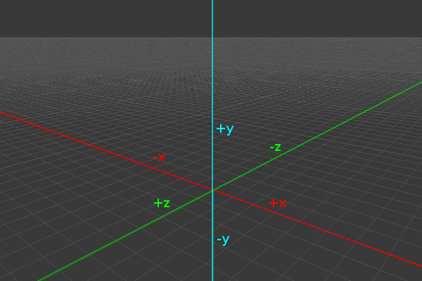
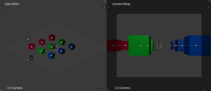
mathematics literature). A right-handed coordinate system
assumes that if the viewer is standing at the origin and
looking towards negative infinity on the Z axis, then the
X axis runs horizontally (left towards negative infinity
and right towards positive infinity), and the Y axis runs
vertically (down towards negative infinity and up towards
positive infinity). The following image demonstrates this
axis configuration:
The jtensors package adheres
to the convention that a positive rotation around an axis
represents a counter-clockwise rotation when viewing the
system along the negative direction of the axis in question.
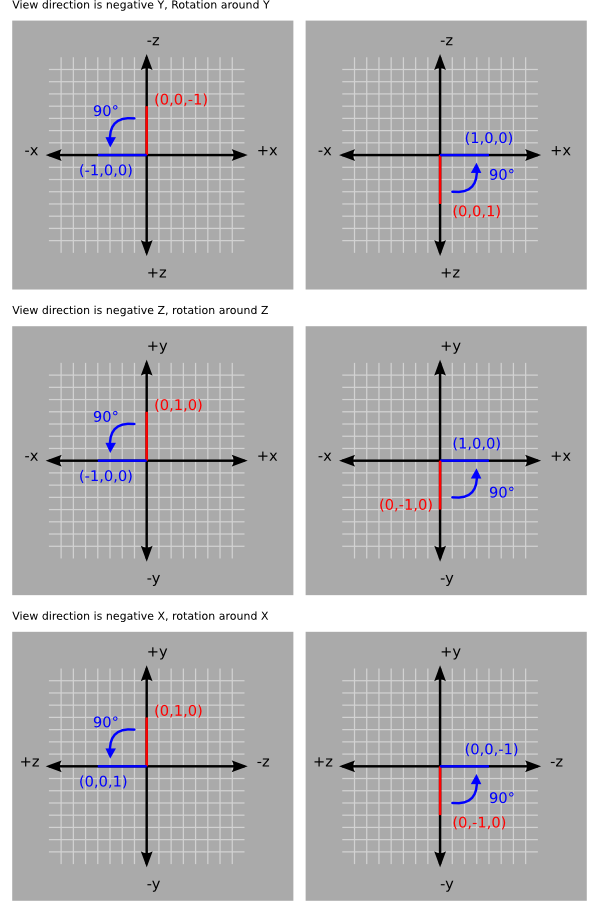
The package uses the following matrices to define rotations
around each axis:
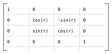
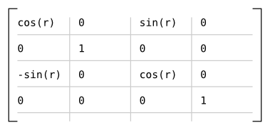
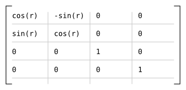
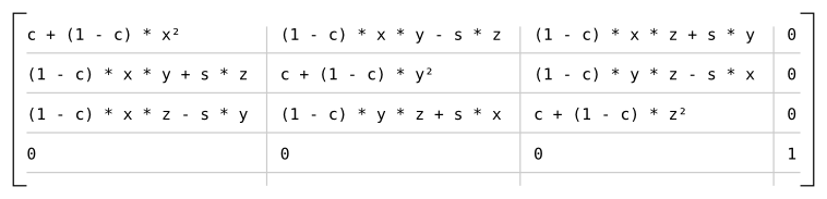
Which results in the following matrix for rotating r radians around the axis given
by (x, y, z), assuming
s = sin(r) and c = cos(r)
[9]:
Types
The io7m-r1 package
uses so-called phantom type parameters
to statically indicate the coordinate systems of vectors, and the
types of transformations that matrices represent. For example, a
value of type RVectorI3F<RSpaceObjectType>
represents an immutable three-dimension vectors with coordinate
specified in object space.
A value of type RMatrixI4x4F<RSpaceTransformViewType>
represents an immutable 4x4 matrix that contains a transformation from
world space to
eye space.
Due to the limited nature of Java's type system, it is obviously
possible for the programmer to deliberately construct vectors and
matrices that do not represent valid coordinates or transforms in
any coordinate space. However, mistakes involving the mixing up
of coordinate systems are rampant in graphics programming, and
in practice, the system as implemented catches many of the mistakes
at compile time.
The package contains the following coordinate system and transform
indexed types:
| Type | Description |
|---|---|
| RMatrixI3x3F<T extends RTransformType> | Immutable 3x3 matrix type |
| RMatrixI4x4F<T extends RTransformType> | Immutable 4x4 matrix type |
| RMatrixM4x4F<T extends RTransformType> | Mutable 4x4 matrix type |
| RMatrixM3x3F<T extends RTransformType> | Mutable 3x3 matrix type |
| RVectorI2F<T extends RTransformType> | Immutable 2D vector type |
| RVectorI3F<T extends RTransformType> | Immutable 3D vector type |
| RVectorI4F<T extends RTransformType> | Immutable 4D vector type |
| RVectorM3F<T extends RTransformType> | Mutable 3D vector type |
| RVectorM4F<T extends RTransformType> | Mutable 4D vector type |
Object space
Object space is the local
coordinate system used to describe the positions of vertices
in meshes. For
example, a unit cube with the
origin placed at the center of the cube would have eight
vertices with positions expressed as object-space coordinates:
cube = {
    (-0.5, -0.5, -0.5),
    ( 0.5, -0.5, -0.5),
    ( 0.5, -0.5,  0.5),
    (-0.5, -0.5,  0.5),

    (-0.5,  0.5, -0.5),
    ( 0.5,  0.5, -0.5),
    ( 0.5,  0.5,  0.5),
    (-0.5,  0.5,  0.5)
  }
In other rendering systems, object space
is sometimes referred to as local space,
or model space.
World space
In order to position objects in a scene, they must be
assigned a transform
that can be applied to each of their
object space vertices
to yield absolute positions in so-called
world space.
As an example, if the unit cube described above was
assigned a transform that moved its origin to
(3, 5, 1), then its
object space vertex (-0.5, 0.5, 0.5)
would end up at
(3 + -0.5, 5 + 0.5, 1 + 0.5) = (2.5, 5.5, 1.5)
in world space.
In the io7m-r1 package,
a transform applied
to an object produces a 4x4
model matrix. Multiplying the model matrix
with the positions of the object space vertices yields vertices in
world space.
Eye space
Eye space represents the coordinate
system of the
camera of
a given visible set.
In eye space, the observer is implicitly fixed at the origin
(0.0, 0.0, 0.0) and is
looking towards infinity in the negative Z direction.
The main purpose of eye space is to simplify
the mathematics required to implement various algorithms such
as lighting. The problem with implementing these sorts of
algorithms in world space is that one must constantly take into
account the position of the observer (typically by subtracting
the location of the observer from each set of world space
coordinates and accounting for any change in orientation of the
observer). By fixing the orientation of the observer towards
negative Z, and the position of the observer at
(0.0, 0.0, 0.0), and
by transforming all vertices of all objects into the same system,
the mathematics of lighting are greatly simplified.
The majority of the rendering algorithms used in the
io7m-r1 package
are implemented in eye space.
In the io7m-r1 package,
the camera produces
a 4x4 view matrix. Multiplying
the view matrix with any given world space position yields
a position in eye space. In practice, the view matrix
v
and the current object's model matrix
m are concatenated (multiplied)
to produce a model-view matrix
mv = v * m
[10], and mv is then
passed directly to the renderer's
vertex shaders to transform the
current object's vertices
[11].
Additionally, as the io7m-r1 package
does all lighting in eye space, it's necessary to transform the
object space normal vectors
given in mesh data to eye space. However, the usual model-view matrix
will almost certainly contain some sort of translational component and possibly
a scaling component. Normal vectors are not supposed to be translated; they
represent directions! A non-uniform scale applied to an object will also deform the
normal vectors, making them non-perpendicular to the surface they're associated
with:
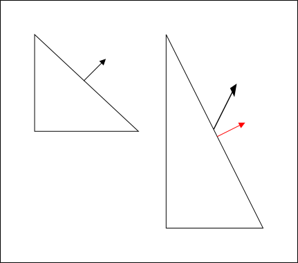
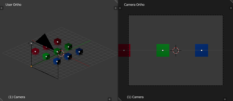
With the scaled triangle on the right, the normal vector is now not perpendicular
to the surface (in addition to no longer being of unit length). The red vector
indicates what the surface normal should be.
Therefore it's necessary to derive another 3x3 matrix known as the
normal matrix from the model-view matrix that
contains just the rotational component of the original matrix. The full
derivation of this matrix is given in
Mathematics for 3D Game Programming and Computer Graphics, Third Edition
[12]. Briefly, the normal matrix is equal to
the inverse transpose of the top left
3x3 elements of an arbitrary 4x4 model-view matrix.
In other rendering systems, eye space
is sometimes referred to as camera space,
or view space.
Clip space
Clip space is a homogeneous coordinate
system in which OpenGL performs clipping
of primitives (such as triangles). In OpenGL,
clip space is effectively a
left-handed coordinate system by default
[13]. Intuitively, coordinates in
eye space are transformed with a
projection (normally either an
orthographic or
perspective projection) such that
all vertices are projected into a homogeneous unit cube placed at
the origin - clip space - resulting
in four-dimensional (x, y, z, w)
positions. Positions that end up outside of the cube are
clipped (discarded) by dedicated
clipping hardware, typically producing more triangles as a result.
A projection effectively
determines how objects in the three-dimensional scene are projected
onto the two-dimensional viewing plane
(a computer screen, in most cases).
A perspective projection
transforms vertices such that objects that are further away from
the viewing plane appear to be smaller than objects that are close
to it, while an orthographic
projection preserves the perceived sizes of objects regardless of
their distance from the viewing plane.
Because eye space is
a right-handed coordinate system by convention, but by default
clip space is
left-handed, the projection matrix used will invert the sign of the
z component of any given point.
In the io7m-r1 package,
the camera produces
a 4x4 projection matrix. The
projection matrix is passed, along with
the model-view
matrix, to the renderer's vertex shaders.
As is normal in OpenGL, the vertex shader produces
clip space coordinates which are then
used by the hardware rasterizer to produce color fragments onscreen.
Normalized-device space
Normalized-device space is, by default, a left-handed
[14]
coordinate
space in which clip space
coordinates have been divided by their own w
component (discarding the resulting w = 1
component in the process), yielding three dimensional coordinates. The
range of values in the resulting coordinates are effectively normalized by the division
to fall within the ranges [(-1, -1, -1), (1, 1, 1)]
[15].
The coordinate space represents a simplifying intermediate step
between having clip space
coordinates and getting something projected into a two-dimensional image
(screen space) for viewing.
The io7m-r1 package
does not directly use or manipulate values in
normalized-device space; it is mentioned
here for completeness.
Screen space
Screen space is, by default, a left-handed coordinate
system representing the screen (or window) that is displaying the actual
results of rendering. If the screen is of width w
and height h,
and the current depth range of the window
is [n, f], then the range of values
in screen space coordinates runs from [(0, 0, n), (w, h, f)].
The origin (0, 0, 0) is assumed to be at
the bottom-left corner.
The depth range is actually a configurable
value, but the io7m-r1 package
keeps the OpenGL default. From the glDepthRange
function manual page:
After clipping and division by w, depth coordinates range from -1 to 1,
corresponding to the near and far clipping planes. glDepthRange specifies a
linear mapping of the normalized depth coordinates in this range to window
depth coordinates. Regardless of the actual depth buffer implementation,
window coordinate depth values are treated as though they range from 0
through 1 (like color components). Thus, the values accepted by
glDepthRange are both clamped to this range before they are accepted.
The setting of (0,1) maps the near plane to 0 and the far plane to 1.
With this mapping, the depth buffer range is fully utilized.
As OpenGL, by default, specifies a depth range of
[0, 1], the positive Z axis
points away from the observer, making the coordinate system left handed.
[8]
Almost all rendering systems use different names to refer to the same
concepts, without ever bothering to document their conventions. This
harms comprehension and generally wastes everybody's time.
[9]
See Mathematics
for 3D Game Programming and Computer
Graphics 3rd Edition, section 4.3.1 for the
derivation.
[10]
Note that matrix multiplication is not commutative.
[11]
The reason for producing the
concatenated matrix on the CPU and then passing it to the shader
is efficiency; if a mesh had 1000
vertices, and the shader was passed m
and v separately, the shader
would repeatedly perform the same mv = v * m
multiplication to produce mv
for each vertex - yielding the exact same
mv each time!
[12]
See section 4.5, "Transforming normal vectors".
[13]
Because normalized device space
is a left-handed system by default, with the viewer looking towards
positive Z, and because the transformation from
clip space to
normalized device space for
a given point is the division of the components of that point
by the point's own w
component.
[14]
The handedness of the coordinate space is dependent on the
depth range
configured for screen space.
[15]
It is actually the division by w that
produces the scaling effect necessary to produce the illusion of perspective
in perspective projections.